Categorygithub.com/stianeikeland/go-rpio/v4
modulepackage
4.6.0
Repository: https://github.com/stianeikeland/go-rpio.git
Documentation: pkg.go.dev

# README

go-rpio

Native GPIO-Gophers for your Pi!

Documentation: GoDoc

go-rpio is a Go library for accessing GPIO-pins on the Raspberry Pi.

It requires no external c libraries such as WiringPI or bcm2835.

There's a tiny bit of additional information over at my blog.
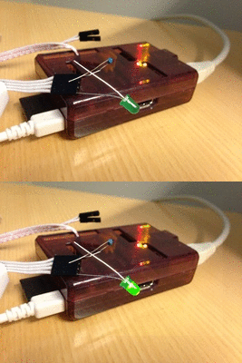
raspberrypi-blink

Releases

  • 1.0.0 - Supports original rpi A/B/B+
  • 2.0.0 - Adds support for rpi 2, by @akramer
  • 3.0.0 - Adds support for /dev/gpiomem, by @dotdoom
  • 4.0.0 - Adds support for PWM and Clock modes, by @drahoslove
  • 4.1.0 - Adds support for edge detection, by @drahoslove
  • 4.2.0 - Faster write and toggle of output pins, by @drahoslove
  • 4.3.0 - Adds support for SPI, by @drahoslove
  • 4.4.0 - Support for disabling interrupts (workaround for #35), by @drahoslove
  • 4.5.0 - Improve rpi 4 support, by @wfd3

Usage

import "github.com/stianeikeland/go-rpio/v4"

If you're using an older go.mod incompatible you should instead use:

import "github.com/stianeikeland/go-rpio"

Open memory range for GPIO access in /dev/mem

err := rpio.Open()

Initialize a pin, run basic operations. Pin refers to the bcm2835 pin, not the physical pin on the raspberry pi header. Pin 10 here is exposed on the pin header as physical pin 19.

pin := rpio.Pin(10)

pin.Output()       // Output mode
pin.High()         // Set pin High
pin.Low()          // Set pin Low
pin.Toggle()       // Toggle pin (Low -> High -> Low)

pin.Input()        // Input mode
res := pin.Read()  // Read state from pin (High / Low)

pin.Mode(rpio.Output)   // Alternative syntax
pin.Write(rpio.High)    // Alternative syntax

Pull up/down/off can be set using:

pin.PullUp()
pin.PullDown()
pin.PullOff()

pin.Pull(rpio.PullUp)

Unmap memory when done

rpio.Close()

Also see example examples/blinker/blinker.go

SPI

setup/teardown

  • rpio.SpiBegin(rpio.Spi0) has to be called first before using any Spi func. It will change pin modes to Spi and initialize default setting.
  • rpio.SpiEnd(rpio.Spi0) should be called at the end, it will switch pin modes to Input.

transferring data

  • rpio.SpiTransmit(byte) or rpio.SpiTransmit(bytes...) will transmit byte or bytes to slave.
  • rpio.SpiReceive(n) will return n bytes received from slave.
  • rpio.SpiExchange(buffer) will simultaneously transmit data from the buffer to slave and data from slave to the same buffer in full duplex way.

settings

  • rpio.SpiSpeed(hz) will set transmit speed of SPI
  • rpio.SpiChipSelect(n) will select chip/slave (ce0, ce1, or ce2) to which transferring will be done
  • rpio.SpiChipSelectPolarity(n, pol) set chip select polarity (low enabled is used by default which usually works most of the time)
  • rpio.SpiMode(cpol, cpha) set clock/communication mode (=combination of clock polarity and clock phase; cpol=0, cpha=0 is used by default which usually works most of the time)

Other

Currently, it supports basic functionality such as:

  • Pin Direction (Input / Output)
  • Write (High / Low)
  • Read (High / Low)
  • Pull (Up / Down / Off)
  • PWM (hardware, on supported pins)
  • Clock
  • Edge detection

It works by memory-mapping the bcm2835 gpio range, and therefore require root/administrative-rights to run.

Using without root

This library can utilize the new /dev/gpiomem memory range if available.

You will probably need to upgrade to the latest kernel (or wait for the next raspbian release) if you're missing /dev/gpiomem. You will also need to add a gpio group, add your user to the group, and then set up udev rules. I would recommend using create_gpio_user_permissions.py if you're unsure how to do this.

PWM modes will still require root.

# Packages

No description provided by the author

# Functions

Close unmaps GPIO memory.
DetectEdge: Enable edge event detection on pin.
DisableIRQs: Disables given IRQs (by setting bit to 1 at intended position).
EdgeDetected checks whether edge event occured since last call or since detection was enabled There is no way (yet) to handle interruption caused by edge event, you have to use polling.
EnableIRQs: Enables given IRQs (by setting bit to 1 at intended position).
Open and memory map GPIO memory range from /dev/mem .
PinMode sets the mode of a given pin (Input, Output, Clock, Pwm or Spi) Clock is possible only for pins 4, 5, 6, 20, 21.
No description provided by the author
ReadPin reads the state of a pin.
SetDutyCycle: Set cycle length (range) and duty length (data) for Pwm pin in M/S mode |<- duty ->| __________ _/ \_____________/ |<------- cycle -------->| Output frequency is computed as pwm clock frequency divided by cycle length.
SetDutyCycleWithPwmMode extends SetDutyCycle to allow for the specification of the PWM algorithm to be used, Balanced or Mark/Space.
SetFreq: Set clock speed for given pin in Clock or Pwm mode Param freq should be in range 4688Hz - 19.2MHz to prevent unexpected behavior, however output frequency of Pwm pins can be further adjusted with SetDutyCycle.
SpiBegin: Sets all pins of given SPI device to SPI mode dev\pin | CE0 | CE1 | CE2 | SCLK | MOSI | MISO | Spi0 | 7 | 8 | - | 9 | 10 | 11 | Spi1 | 16 | 17 | 18 | 19 | 20 | 21 | Spi2 | 40 | 41 | 42 | 43 | 44 | 45 | It also resets SPI control register.
SpiChipSelect: Select chip, one of 0, 1, 2 for selecting slave on CE0, CE1, or CE2 pin.
SpiChipSelectPolarity: Sets polarity (0/1) of active chip select default active=0.
SpiEnd: Sets SPI pins of given device to default (Input) mode.
SpiExchange: Transmit all bytes in data to slave and simultaneously receives bytes from slave to data.
SpiMode: Set polarity (0/1) and phase (0/1) of spi clock default polarity=0; phase=0.
SpiReceive receives n bytes from slave.
SpiSpeed: Set (maximal) speed [Hz] of SPI clock.
SpiTransmit takes one or more bytes and send them to slave.
StartPwm starts pwm for both channels.
StopPwm: Stop pwm for both channels.
TogglePin: Toggle a pin state (high -> low -> high).
WritePin sets a given pin High or Low by setting the clear or set registers respectively.

# Constants

Pin mode, a pin can be set in Input or Output, Clock or Pwm mode.
Edge events.
Which PWM algorithm to use, Balanced or Mark/Space.
Pin mode, a pin can be set in Input or Output, Clock or Pwm mode.
Edge events.
Pin pull-up/down for pins 15:0.
Pin pull-up/down for pins 31:16.
Pin pull-up/down for pins 47:32.
Pin pull-up/down for pins 57:48.
State of pin, High / Low.
Pin mode, a pin can be set in Input or Output, Clock or Pwm mode.
State of pin, High / Low.
Which PWM algorithm to use, Balanced or Mark/Space.
Edge events.
Pin mode, a pin can be set in Input or Output, Clock or Pwm mode.
Pull Up / Down / Off.
Pin mode, a pin can be set in Input or Output, Clock or Pwm mode.
Edge events.
Pin mode, a pin can be set in Input or Output, Clock or Pwm mode.
SPI devices.
aux.
aux.

# Variables

No description provided by the author

# Type aliases

No description provided by the author